******* WARNING*******
This product is not intended for
uneducated users. It is provided for
experienced rebreather and mixed gas users ONLY. If you have not been properly trained by an internationally
recognized technical certification agency and/or don't have a firm grasp of
electronics then DO NOT USE THIS STUFF. God forbid you actually use it
underwater, everyone knows water and electronics don’t mix.
This design, if used as part of a life
support system, could indirectly kill you, and it probably has faults. The designer does not warrant that it won't
get you killed, or that it will produce safe, reliable, results. This dive product is experimental, and if
you choose to use it than you do so at your own risk. Diving in general is fraught with risk and playing with things
you don’t take the time to understand and verify adds significantly more risk.
Construction
of sensor/display units
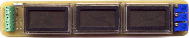
For
#’s 1_PPO2, 3__PPO2, and 1_3_PPO2
Read through
this entire procedure before touching a soldering iron, screw driver ......
Board
preparation:
The printed circuit board (PCB) is only
rough-cut and you must trim the edges to the proper dimensions. The PCB has a .008” perimeter trace on the
top layer that is the outline of the finished product. If you use this outline as a guide the
populated PCB with a battery will fit into a 1-1/4” internal diameter
tube. There is a little extra built
into each end to allow for different mounting methods. I typically trim to the
outline by using a 1” belt sander and go about halfway into the trace. The trace will then usually peel off. Remember that there are traces on the bottom
as well so don’t go to far.
Parts
Installation:
1) Turn the trim
pot(s) on the back of the DPM(s) fully clockwise.
Perform sub steps
a, b, c below for the 3-display/sensor unit.
a) Apply power to
each DPM, pin 1(+9V) and pin3 (ground).
b) Note the
voltage between pin 8 and pin 10 of each DPM; it should be a little above
100mV.
c) Adjust each
DPMs voltage output on pin 8 to the lowest read value noted in step 1b.
d) For example,
you did step 1, 1a, and 1b and got values of 100mV, 105mV and 95 mV. In step 1c you would go back and adjust the
two high reading displays of 100 and 105mV to read 95mV using the trim pot on
the back of the display.
2) Epoxy over the
pot adjustment screws to seal the unit(s).
3) Install the
battery clips on the PCB. Make sure you
place the positive clip in the positive position and the negative clip in the
negative position. Verify by having a
battery on hand to look at. Or put the
clips on the battery and hold it in place with a rubber band while you solder
in the clips. Remove the battery when done.
4) Install the
DPM(s) on the PCB with pin 1 in the hole with the square solder pad.
5) Install the
sensor calibration pot(s). I would
suggest turning the calibration screw all the way counter clockwise so you’ll
have a reading the first time you attach sensors.
6) Install the
terminal block. If desired do not
install the terminal block and solder the sensor wires directly to the
board. If you solder the wires directly
to the board do not have the sensors attached on the other end as a precaution.
7) Install the
decimal jumper (for the one display board) and the sensor load resistor(s) if
necessary (DO NOT place a jumper here if a load resistor is not necessary that
would short the sensor outputs and be very very bad).
8) Reed switches:
These reed switches can take more pressure then you could give then in an
ambient pressure housing underwater, but put a little pressure on the wire
where it goes through the glass and your sure to break one. To say these are delicate during
installation is an understatement. One
end of the glass tube has two wires and the other end has one wire. On the double wire end you’ll need to cut
off one of the wires for one switch and then the other wire for the other
switch. Use some small, sharp, and
pointed right angle cutters to do this.
You can leave a little stub on the end you cutoff; when cutting the
already bent wire I cut just before the first bend and also leave about the
same length on the straight one. When
bending the wires to fit the through holes on the board use small needle nose pliers. Estimate where the wire will need to be bent
on each end to make it even on both sides and make it through the holes. Hold one side of the pliers close to the
glass tube and bend the free end of the wire 90 degrees. Double-check where the other end needs to be
bent. Again, hold one side of the
pliers close to the glass tube and bend the free end of the wire 90
degrees. On the two-wire end, the
needle nose pliers can hold both the left over stub and the wire your bending
flat in its jaws. Then just bend the
longer wire across the corner of the pliers. Remember do not put any stress on
the glass.
9) Install the
normally open, with magnet present, reed switch in the location marked NO.
10) Install the
normally closed, with magnet present, reed switch in the location marked NC.
Verification,
test, and operation:
1)
Before attaching the battery deflux the back of the
PCB. Check that there are no solder
bridges. Pay special attention to the
bottom traces that run between pins being sure they’re not solder bridged to
adjacent pins. Trim the excess lead
material from the bottom of the board.
Double check your work, five minutes of checking could save you from
smoking something.
2)
Install the battery and without a magnet present verify that
the power comes on and that there is no voltage at the terminal block between
the sensor ground and the sensor positive connections. WARNING: There is no reverse polarity protection,
be sure that the battery terminals are connected correctly otherwise you could
damage the DPM.
3)
Place a magnet near the NC reed switch and verify that the
backlight comes on.
4)
Place a magnet near the NO reed switch and verify that the
power turns off.
5)
For the 1 display/sensor board check that the decimal point
is in the proper position.
6)
Attach the sensor leads to the terminal block, being careful
not to short the sensor leads to each other. Better yet the sensors should be
on connectors and disconnected.
7)
Connect the sensors.
8)
Adjust the Sensor Calibration pot(s) so that the display(s)
read correctly.
9)
Play around with it.
******* WARNING*******
This product is not intended for
uneducated users. It is provided for
experienced rebreather users ONLY. If
you have not been properly trained by an internationally recognized technical
certification agency and/or don't have a firm grasp of electronics then DO NOT
USE THIS STUFF. God forbid you actually use it underwater, everyone knows water
and electronics don’t mix.
This design, if used as part of a life
support system, could indirectly kill you, and it probably has faults. The designer does not warrant that it won't
get you killed, or that it will produce safe, reliable, results. This dive product is experimental, and if
you choose to use it than you do so at your own risk. Diving in general is fraught with risk and playing with things
you don’t take the time to understand and verify adds significantly more risk.
Construction
of PO2 display units
For # SS-PPO2-1
Read through
this entire procedure before touching a soldering iron, screw driver ......
Board
preparation:
The printed circuit board (PCB) is only
rough-cut and you must trim the edges to the proper dimensions. The PCB has a .008” perimeter trace on the
top layer that is the outline of the finished product. Use this outline as a guide to removing the
excess material. I typically trim to
the outline by using a 1” belt sander and sand about halfway into the
trace. The trace will then usually peel
off. Remember that there are traces on
the bottom as well so don’t go to far.
Backlighting:
Use schematic ss-ppo2-1 for
reference. There are a number of ways
to configure the backlighting to suit your needs and application. Component location R4 on the board is used
to adjust the display backlighting brightness and will affect your power
consumption. If you would like maximum
brightness and are using a 9V supply install a jumper across R4. If you would like to get longer battery run
times but with reduced brightness install a 100W resistor in R4. With a standard 9V battery and R4 jumpered
the battery will last ~3 hours. With a
100W resistor a 9V
battery will last ~14 hours. You can
play around with the value of R4 to balance your brightness -vs.- power
duration needs. WARNING: If a supply voltage of
greater then 9V is used then a resister with a value of 150W or higher
must be used to avoid damage to the display.
To externally activate the backlighting a
remote switch should connect the BL connector on the display board with supply
ground. If you would like the
backlighting to come on whenever power is supplied then place a jumper across
J1 on the display board.
Parts Installation:
1) Before
installing the DPMs turn the trim pot on the back of the DPMs fully clockwise.
a) Apply power to
each DPM, pin 1(+9VDC to +14VDC) and pin3 (ground).
b) Record the
voltage across pin 8(+) and pin 10(-) of each DPM; it should be a little above
100mV.
c) Adjust each
DPMs voltage output on pin 8 to the lowest read value in step 1b using the trim
pot on the back of the display.
d) For example,
you did step 1, 1a, and 1b and got values of 100mV, 105mV and 95 mV. In step 1c you would go back and adjust the
two high reading displays of 100 and 105mV to read 95mV using the trim pot on
the back of the display.
2) Epoxy over the
pot adjustment screws to seal the units.
3) Install the
DPMs on the PCB with pin 1 in the hole with the square solder pad.
4) Install the
sensor calibration pot(s). I would
suggest turning the calibration screws all the way counter clockwise so you’ll
have a reading the first time you attach sensors. Also, the pots pictured have the adjustment screws pointing up
(perpendicular to the face of the board), but if you’d like the adjustment
screws pointing out (parallel with the face of the board), order the same part
number specified for the #3_PPO2 board.
5) Install the
terminal block, if desired do not install the terminal block and solder the
wires directly to the board. If you solder the wires directly to the board do
not have the sensors attached on the other end as a precaution.
6) Install the
backlight brightness resistor R4, backlight jumper J1 (if you want backlighting
on all the time)
7) Install the
sensor load resistors if necessary. DO
NOT place a jumper here if a load resistor is not necessary that would short
the sensor outputs and be very very bad.
Again do not have the sensors attached on the other end as a precaution.
Verification,
test, and operation:
1)
Before attaching the battery deflux the back of the
PCB. Check that there are no solder
bridges. Pay special attention to the
bottom traces that run between pins being sure they’re not solder bridged to
adjacent pins. Trim the excess lead
material from the bottom of the board.
Double check your work, five minutes of checking could save you from
smoking something.
2)
Apply power. WARNING:
There is no reverse polarity protection, be sure that the power is connected
correctly otherwise you could damage the DPM.
3)
With power on check to see that there isn’t any stray supply
voltage from SG to S1, S2, and S3.
4)
Attach the sensor leads to the terminal block, being careful
not to short the sensor leads to each other.
Better yet the sensors should be on connectors and disconnected.
5)
Connect the sensors.
6)
Adjust the Sensor Calibration pot so that the display reads
correctly.
7)
Play around with it.