|
bracelet thomas sabo
thomas sabo sale
thomas sabo charm
thomas sabo jewellery
thomas sabo outlet
vibram five fingers outlet
vibram five fingers sale
vibram five fingers
vibram chaussure
vibram france
The display's listed below are currently what I have available for sale. I'm selling either the bare printed circuit board and you can acquire all the parts yourself from the venders listed in the associated parts_list.pdf. Or you can save yourself some time and order the board from me with the parts needed for assembly. Hell if ya want, print out the associated schematic.pdf and hard wire your own. If your wondering what you get in the parts kit, what you see in the associated picture is what you get. Or look at the parts list and that's also the extent of what you'll receive. Some of the pictures of my boards on this page show them without the green solder mask. All boards are now shipped with solder mask. Assembly required All boards come as kits unassembled, except for the Gorilla Boards. Gorilla Board II The Gorilla II board is the latest incarnation of my PO2 display board series and incorporates many improvements. The display of one, two, or three sensors can be specified by the user. All display board operating parameters, such as the number of sensors to displayed, is accomplished using a single push button. This push button also controls power to the board and activation or deactivation of the backlight. Please visit this link for more information. All orders for this display board, and housing, go through Gorilla Diving Products.
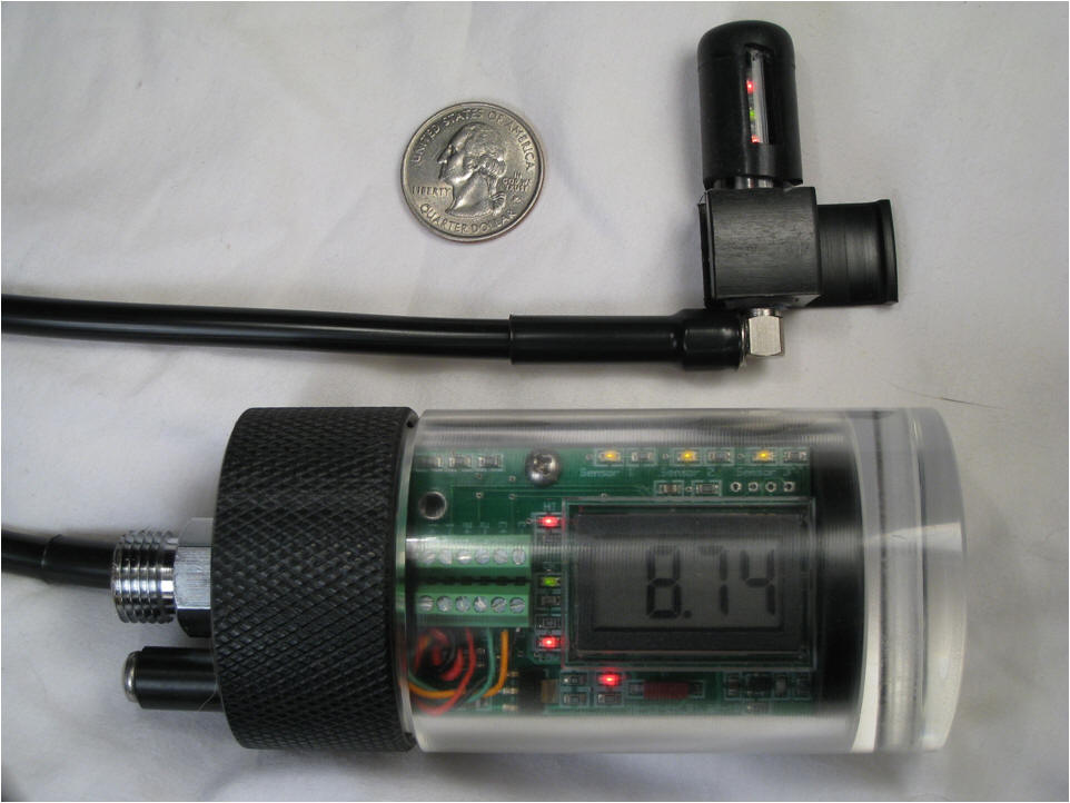
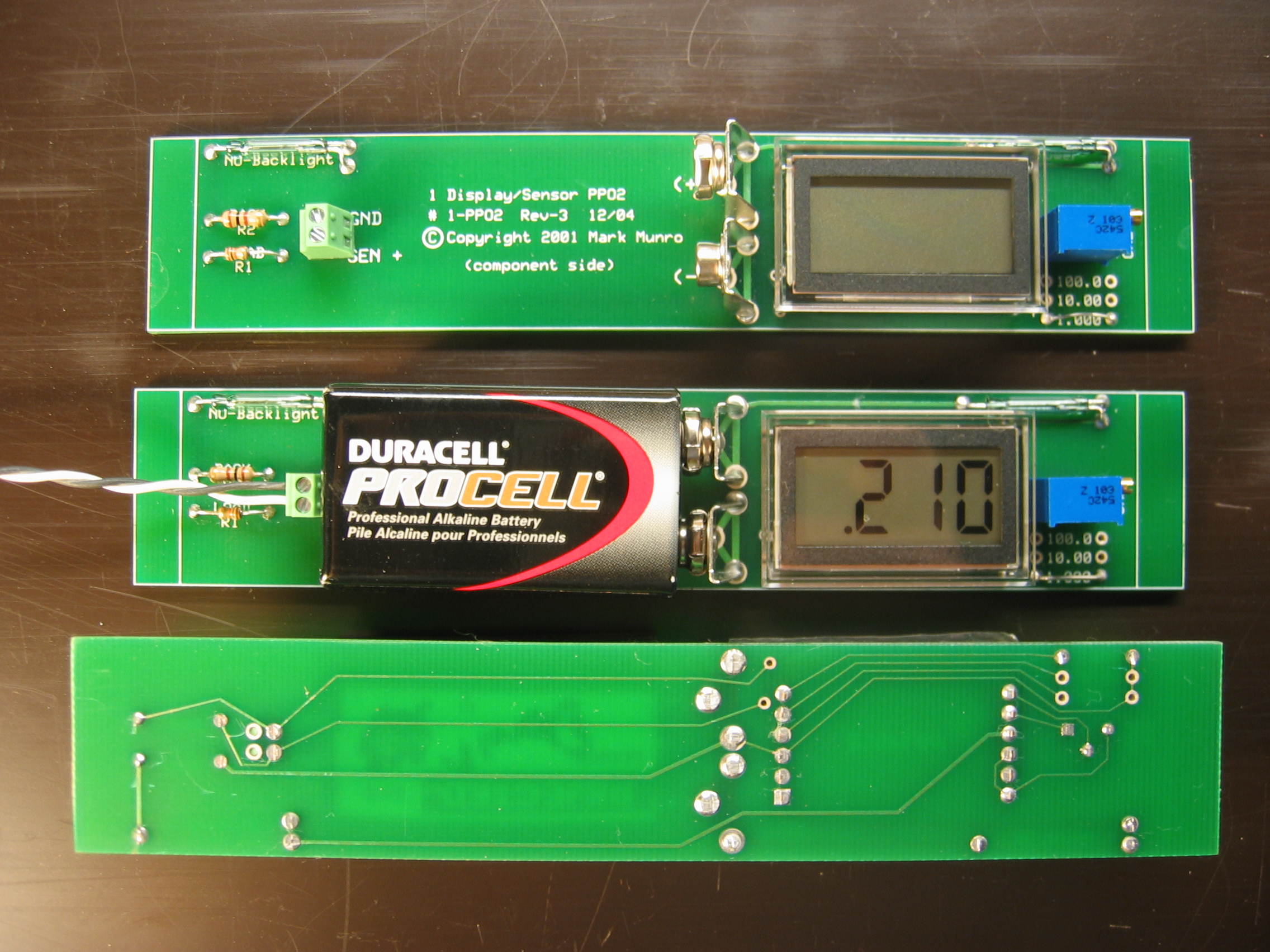
1-PPO2 Reads one sensor and has one display. This board is a one display/sensor unit I use on my O2 breather but it could also be used on an SCR breather for a verification of loop PPO2 or it could be used on the surface as a mix analyzer. This unit has one display that shows the reading of one sensor. All operations are the same as the 3-PPO2 board with the exception that there is a jumper location to move the decimal point on the display. This board is a one display/sensor unit I use on my O2 breather but it could also be used on an SCR breather for a verification of loop PPO2 or it could be used on the surface as a mix analyzer. This unit has one display that shows the reading of one sensor. All operations are the same as the 3-PPO2 board with the exception that there is a jumper location to move the decimal point on the display.
(Click on the image for full size) $20, Board 1-3PPO2 Reads three sensors and has one display. This board is a one display/three sensor setup. It has one display that is switched between three sensors. All operations are the same as the 3-PPO2 board with the exception that there is only one display. The sensor that the display is reading is determined by using a remote 2-pole 3-position switch. That's what the wires are for you see on the right hand side of the board. It was developed to be a secondary display but could be used as a primary.
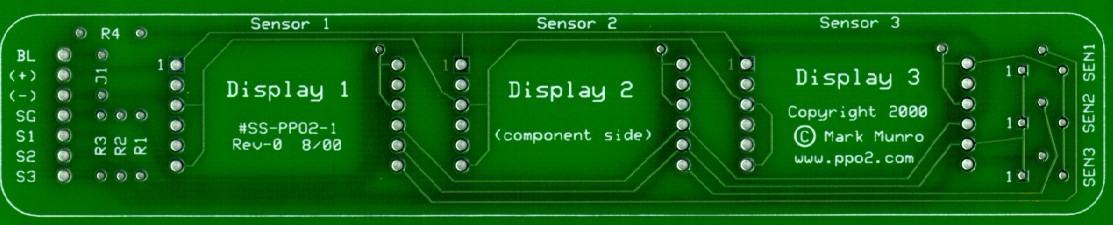
(Click on the image for full size) $20, Board SS-PPO2-1 Reads three sensors, has three displays, and uses a remote power source. This board has three displays each showing the readings of a separate sensor. Power is provided from a remote source. Back lighting can be configured to be switched on externally or on whenever power is applied, also brightness of the back light, and hence battery life, is adjustable by an onboard resistor. There is also a location for sensor load resistors if needed. The trim pots screws can be either upward facing, as shown, or ones that would come out to the right.
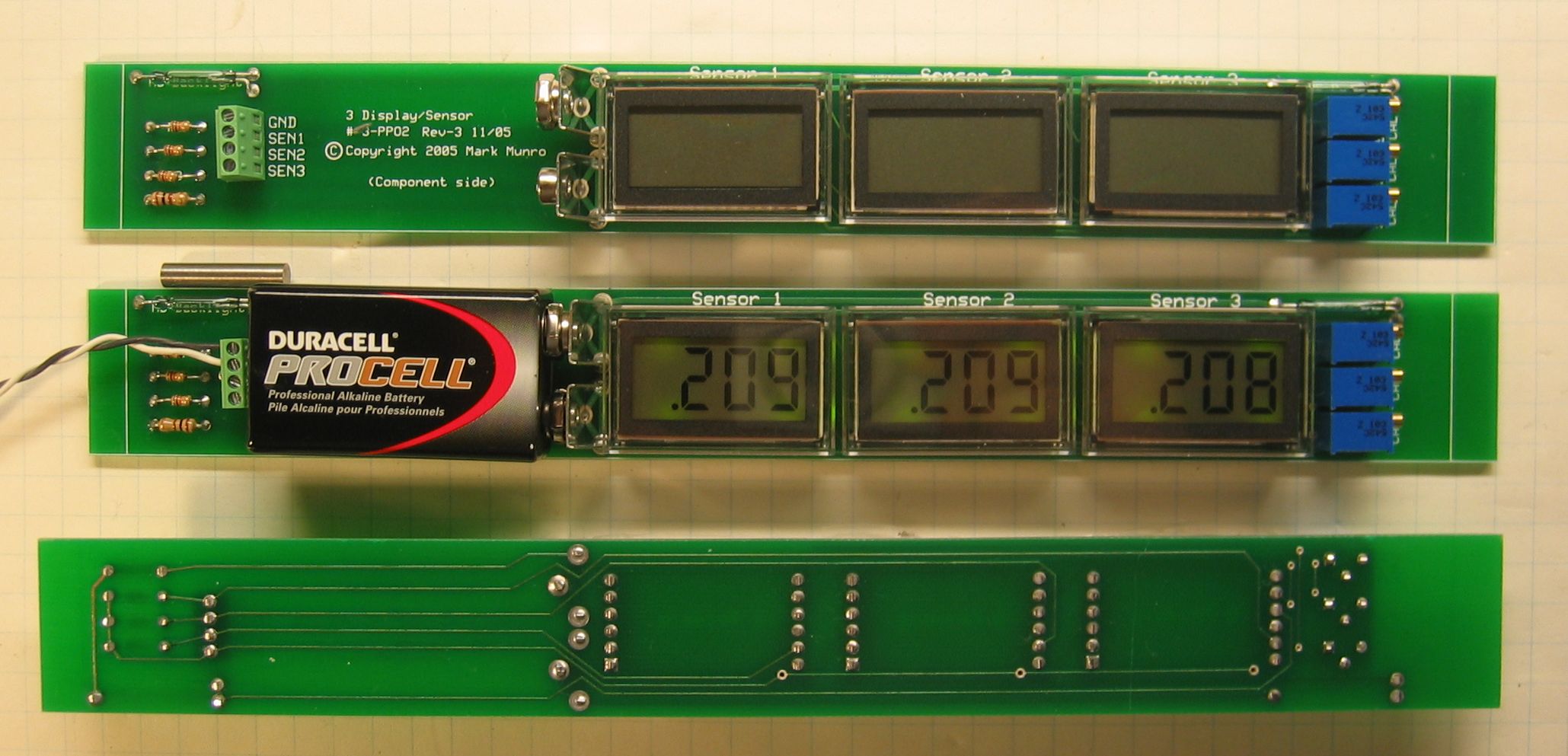
(Click on the image for full size) $20, Board 3-PPO2
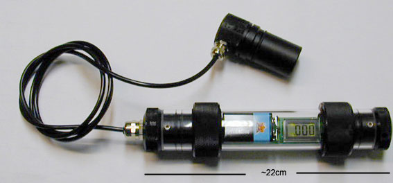
The three
displays run off a single 9V battery. Power is turned on by
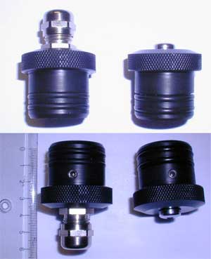
removing a magnet external to the housing which is left in place when
not in use (detail). The magnetic reed switch for power can be seen on the printed
circuit board (PCB) just above and to the left of the blue trim
pots. Each display has back lighting which is activated by placing
a magnet external to the housing close to the magnetic reed switch
located on the PCB just above the header connector. The housing is
a 1-1/4" I.D. Lexan tube and
(Click on the image for full size)
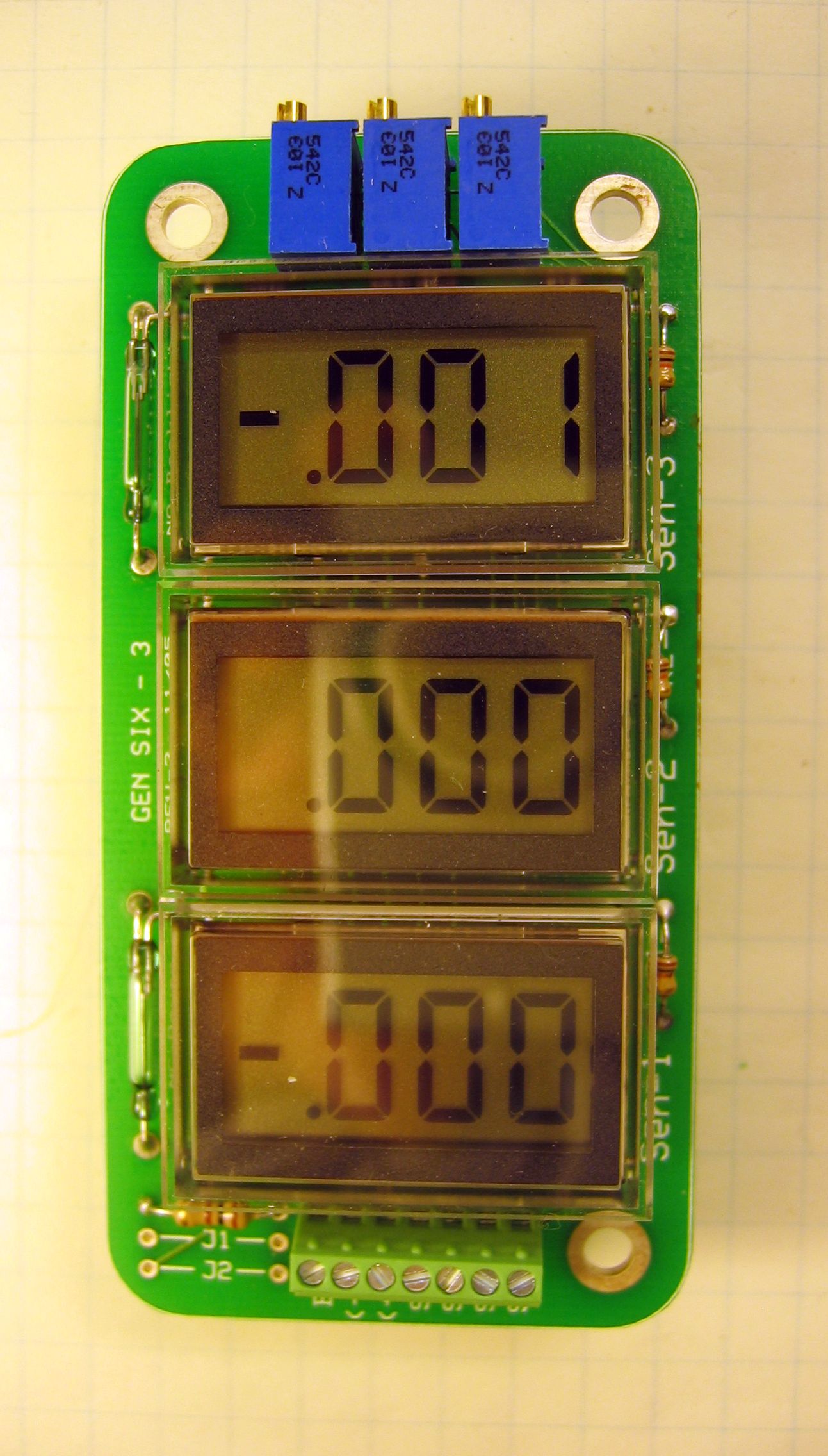
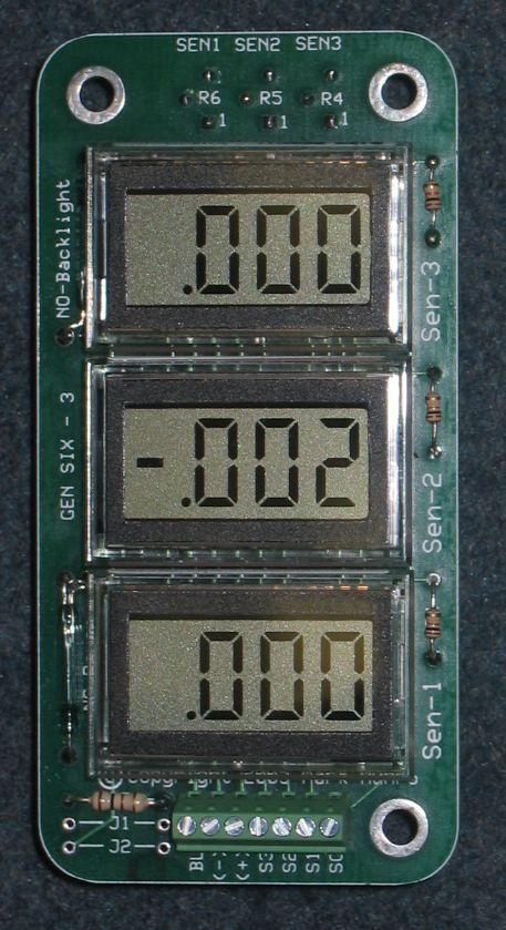
$25, Board Gen Six - 3
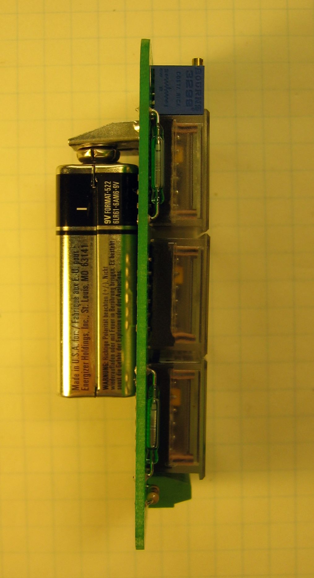
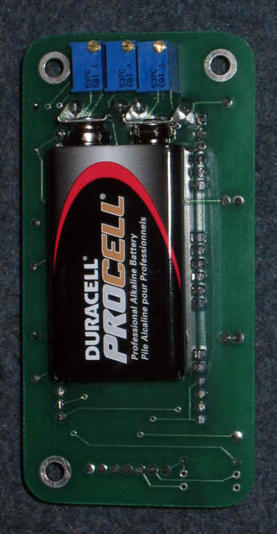
The three displays run off a single 9V battery mounted on the back or a 9V - 14VDC external power source. Power is turned on by removing a magnet external to the housing which is left in place when not in use. The magnetic reed switch for power can be seen on the printed circuit board (PCB) in the upper left of the first photo below, to the left of the upper most display. Each display has back lighting which is activated by placing a magnet external to the housing close to the magnetic reed switch located on the PCB to the left of the lower display . The sensor calibration trim pots can be mounted on either side of the board and can use top or side mounted trim screws. Dimensions: 1-13/16 wide x 3-5/8" long x 1-3/16" deep with battery or 1/2" deep without battery. 4.5 cm wide x 9.3 cm long x 3 cm deep with battery or 1.3 cm deep without battery
(Click on the image for full size)
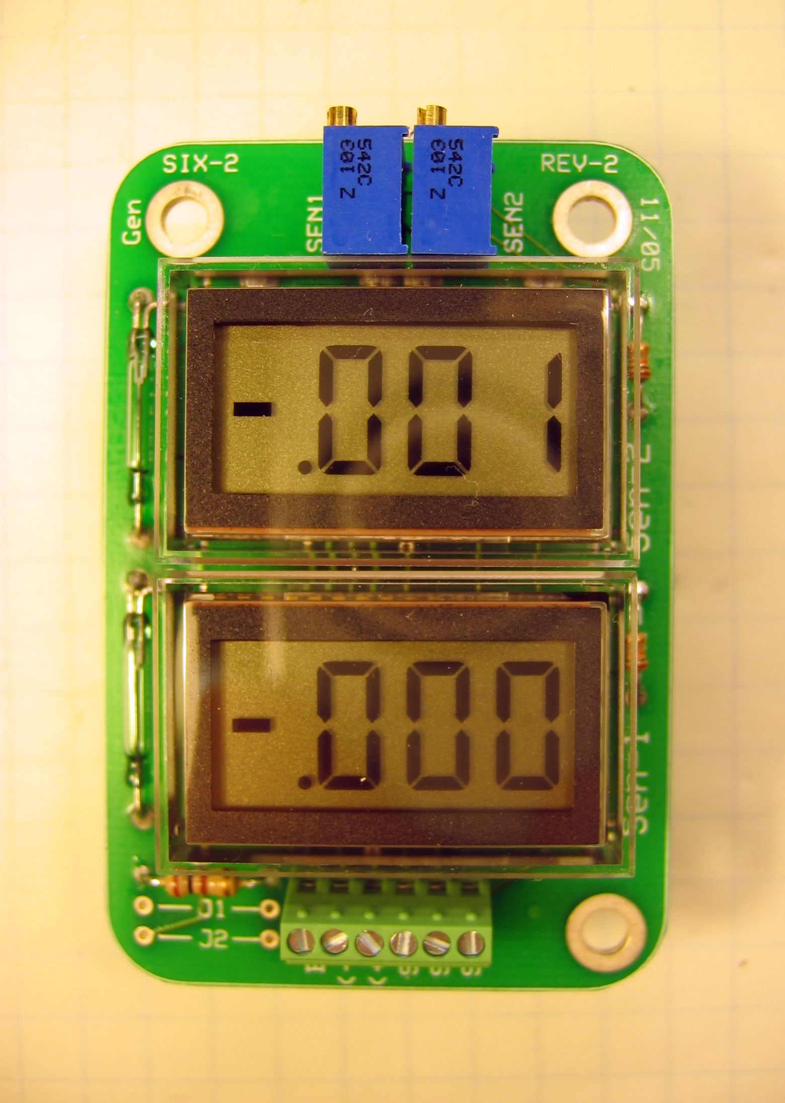
$25, Board Gen Six - 2
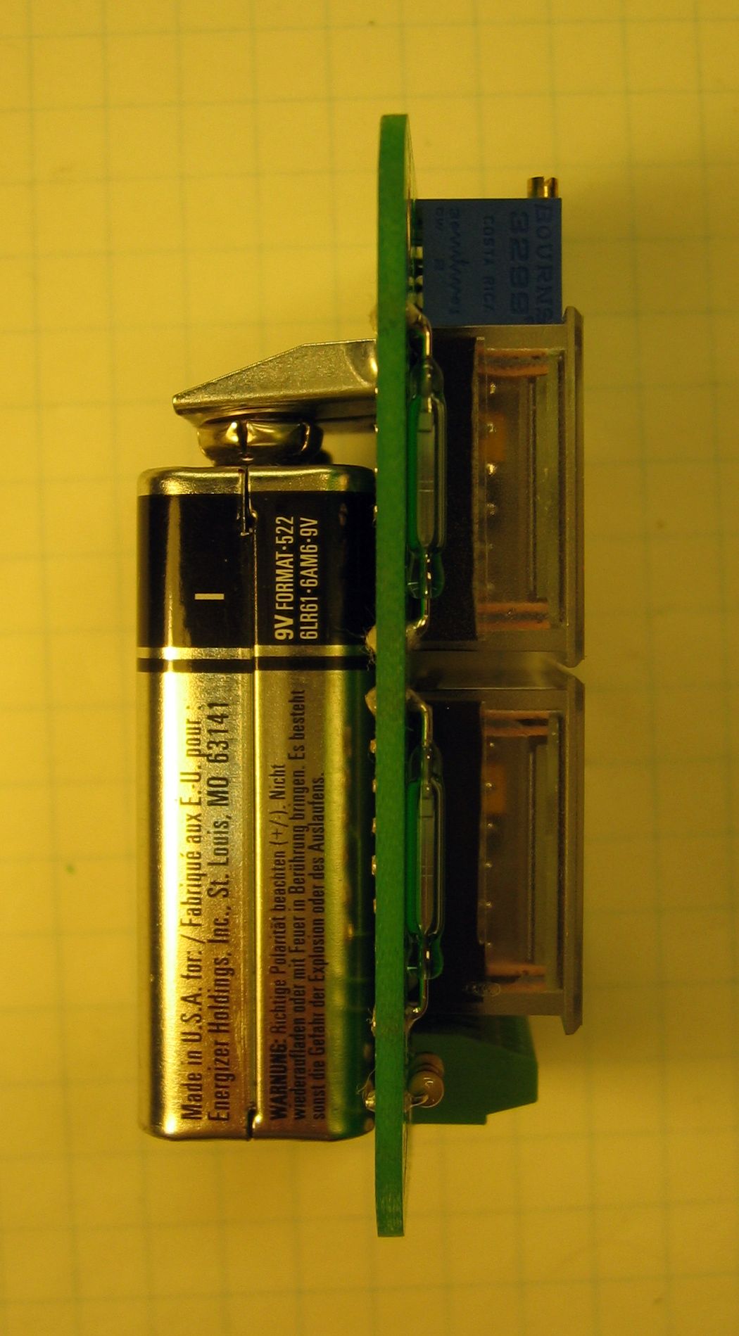
The two displays run off a single 9V battery mounted on the back or a 9V - 14VDC external power source. Power is turned on by removing a magnet external to the housing which is left in place when not in use. The magnetic reed switch for power can be seen on the printed circuit board (PCB) in the upper left of the first photo below, to the left of the upper most display. Each display has back lighting which is activated by placing a magnet external to the housing close to the magnetic reed switch located on the PCB to the left of the lower display . The sensor calibration trim pots can be mounted on either side of the board and can use top or side mounted trim screws. Dimensions: 1-13/16 wide x 2-3/4" long x 1-3/16" deep with battery or 1/2" deep without battery. 4.5 cm wide x 7 cm long x 3 cm deep with battery or 1.3 cm deep without battery
(Click on the image for full size)
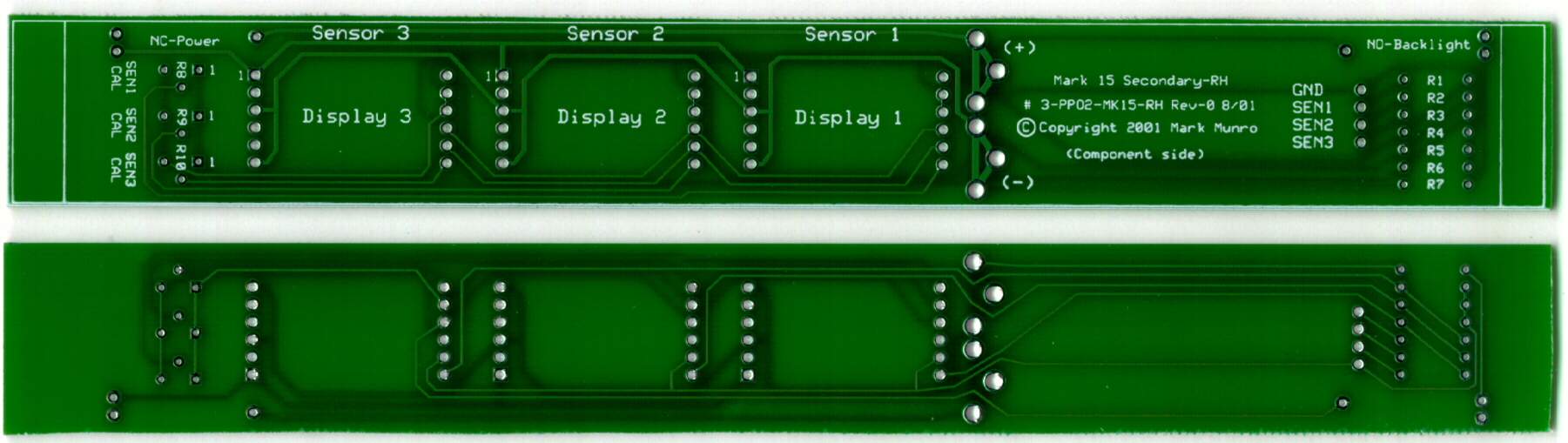
$25, Board #MK15-PPO2 Exactly like the #3-PPO2 board except it's a mirror image, meaning it's designed to come around your right side instead of your left. These boards are specifically made for the MK15/BMR500 so they can't be used for home builts unless you're designing around the MK15/BMR500 circuitry.
(Click on the image for full size) Parts list Housings I don't sell housings for these boards but: Drawings of the end caps I use are here. Also Martin at Tec Me is selling end plugs, tubing, and complete housings at a reasonable cost.
The links below are a must read if your interested in purchasing a board. Operating Principles, A description of the why and how of display board operation. How to Construct, A page with the instruction sheet on how to assemble a board. Construction Photo's, Photo's and descriptions of constructing a 3 display board. |